Notice: This user guide is based on the legacy connector.
We recommend using our new connectors instead, as they are easier to use and actively maintained. This legacy documentation may not be up to date.
We recommend using our new connectors instead, as they are easier to use and actively maintained. This legacy documentation may not be up to date.
We have renamed some core concepts in Speckle to be more widely understandable.
- Streams have been renamed to projects
- Branches have been renamed to models
- Commits have been renamed to versions
Getting started
To install this Connector and add your Speckle account, follow the instructions in the Speckle Manager section. Speckle currently supports both Rhino 6 and Rhino 7. Once installed, you can find the connector by running theSpeckle command in Rhino. This should open a new pop-up window with the Desktop UI (the old version of Speckle used the SpecklePanel command for this).
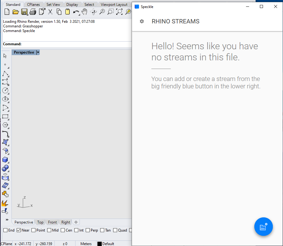
User interface
This connector uses our shared Desktop UI.Once the Desktop UI panel is open, go ahead and create a new project (or add an existing one) to the current file. Once the Rhino
.3dm file is saved, the projects associated with that file will be saved too.
Sending
Sending objects to Speckle can be done in multiple ways.- Default method sends
Everythingfrom Rhino. This includes all document objects and project info.
Layersoption will send objects on the selected layers.
Project Informationadds the selected project information as views to the project.
Selectionsends only the selected objects.
Base object properties, which can be recreated on the receiving end.
Receiving
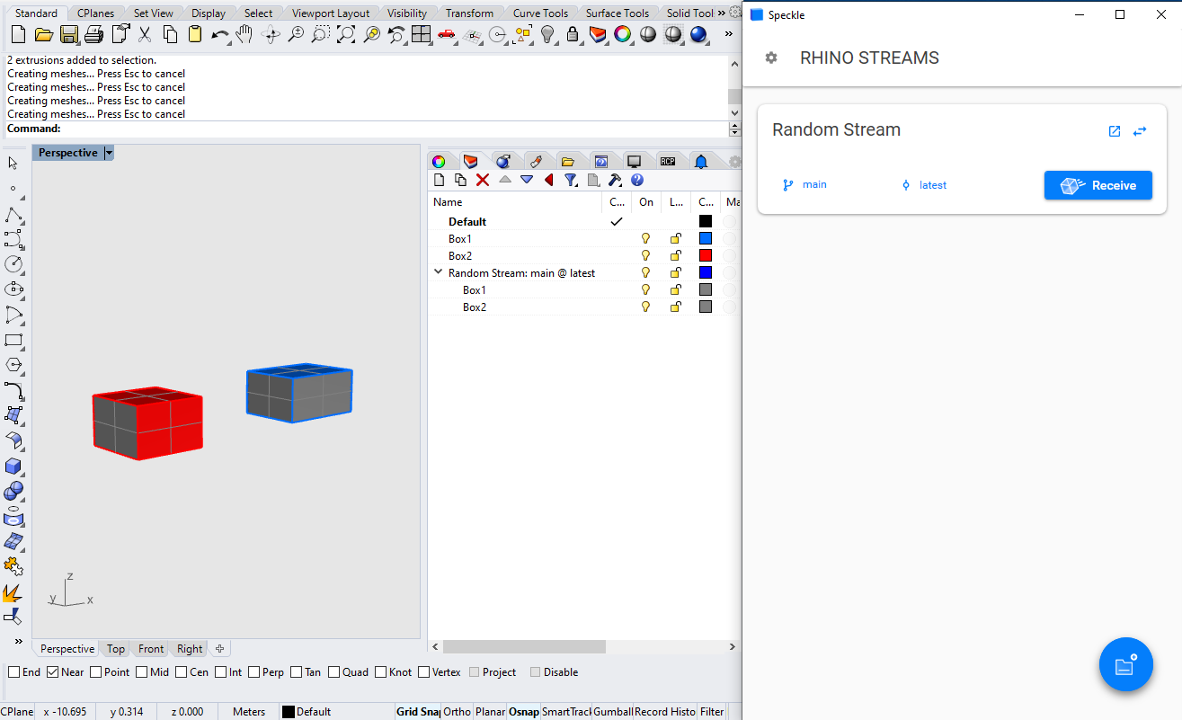
In order to receive data from a Speckle project, you’ll first need to add that to your active document. If the project already exists on the server it will automatically be listed. You can also use the search bar to find the project you are looking for👀.
Receive mode.

model and the version you want to receive. Once you are done with the selection, go ahead and click on the 🔵 Receive button. This will display a progress bar (just like the sending operation) and, if successful, will add the received objects to the current document.

<PROJECT_NAME>: <MODEL_NAME> @ <VERSION>.
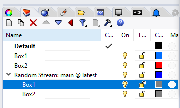
- The original layers of the sent objects
- The layers created by Speckle when receiving the data back
Rhino Mapper
Speckle 2.0 lets you tag Rhino geometry as Speckle BIM elements, so you can send objects like lines and surfaces as beams and floors! This means you can bring in your Rhino geometry directly as native Revit family elements 💥
Getting started
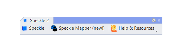
Open the Rhino Mapper panel by clicking on the Speckle Mapper button on the Speckle toolbar, or by using theSpeckleMappings command.
Features
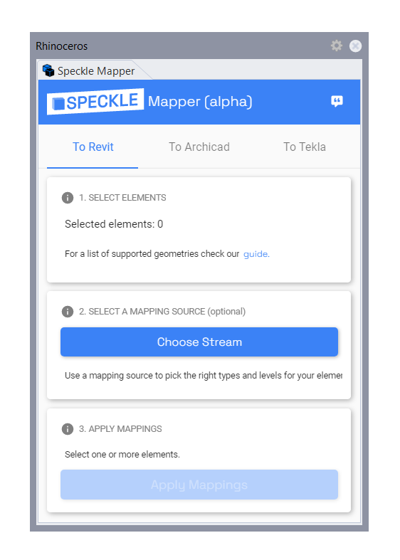
Assigning or removing Speckle BIM tags from geometry objects is easy:- Select the geometry you would like to map to a BIM element
- (Optional) Click
Choose projectto select the model of the Speckle project that contains your Revit families and levels. If none is selected, a default mapping will be used if available. - Click
Apply Mappings
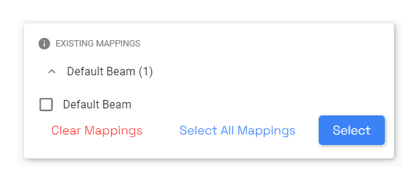
Attribute User Text property if they have been flagged as BIM elements while sending to a project. You can see which objects in your model have been mapped at the bottom of the Speckle Mapper UI.
To remove a mapping, click the checkbox next to the existing mapping and then click Clear Mappings.
If no mapping options appear when you select a geometry object, that means there are currently no supported mappings for that object! If you think there should be, give us feedback using the feedback button on the top right corner.
Creating walls
Walls can be mapped with three different options, depending on the type of surface geometry you’ve selected:- For vertically planar single surfaces, you can map a wall by its profile curve or by its base curve.
- For nonplanar single surfaces, you can map a wall as a
FaceWall. - The default wall option will generate a wall schema by the surface’s base curve.